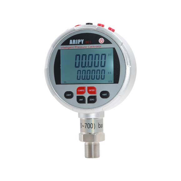
Operating Guide for the Intelligent Pressure Calibrator
As a critical piece of equipment in modern industrial applications, the proper use of the intelligent pressure calibrator is essential for ensuring measurement accuracy and operational efficiency. Below is a detailed breakdown of the core operating procedures to help you quickly master its usage.
1. Pre-Operation Preparations
Before using the smart pressure calibrator, ensure all preparatory steps are completed. This includes inspecting the instrument’s operational status, verifying stable power and signal connections, and confirming the working environment meets the device’s requirements. Additionally, familiarize yourself with the interface and functional settings to effectively utilize various measurement and calibration features.
1.1 Equipment Inspection
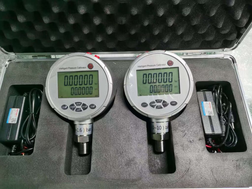
First, carefully inspect the exterior of the smart pressure calibrator for any signs of damage. Simultaneously, ensure all interfaces maintain good sealing performance to prevent air or fluid leaks. Furthermore, verify the power connection status. If the calibrator uses an internal battery, confirm sufficient battery charge—typically indicated by a green charging light. When using an external power source, carefully check that the voltage matches the instrument’s specifications. Finally, select an appropriate pressure calibrator based on the range of the device under test to avoid potential damage from overrange operation.
1.2 Environmental Conditions
When using the intelligent pressure calibrator, ensure it operates within suitable environmental conditions. Avoid placing it in strong electromagnetic fields, high temperatures (exceeding 50°C), or humid environments to prevent sensor interference or damage. Additionally, when calibrating negative pressure equipment, always verify that the calibrator supports the negative pressure range to ensure calibration accuracy.
1.3 Connecting the Tested Equipment
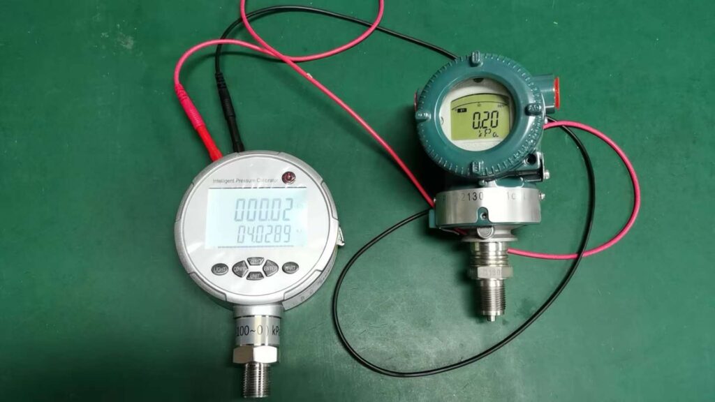
Connect the smart pressure calibrator to the tested instrument using the dedicated high-pressure hose, ensuring a secure seal at the connection point. For example, reinforce threaded connections by wrapping them with PTFE tape. When calibrating transmitters, connect them in series with a 250Ω resistor.
2. Key Operational Procedures
After connecting the device under test, proceed with the core operational steps. These are critical for ensuring calibration accuracy and reliability.
2.1 Power-Up and Initialization
First, press the “Power” button to activate the calibrator. The LCD screen will display the current measurement status, which may include key information such as pressure values, units, and current readings. During this process, wait patiently until the calibrator completes its self-test and shows “Ready” or stable readings, indicating it is prepared for subsequent calibration tasks.
2.2 Zero Calibration
Before performing zero calibration, ensure the system under test is fully depressurized to zero pressure. With no pressure applied, lightly press the “Zero Calibration” button. The calibrator will automatically capture and store the sensor’s zero-point value, effectively minimizing the impact of environmental factors.
3. Specialized Operating Guidelines for Transmitter Calibration
When performing transmitter calibration, a series of specialized operational steps must be followed. These steps ensure calibration accuracy and efficiency, helping users better understand and master the calibration process.
3.1 Air Tightness Inspection
Pressurize the transmitter to its full scale range (e.g., 2.5 MPa) using a hand pump. Subsequently, disconnect the pressure source, seal the transmitter, and wait for 15 minutes. If the pressure drop does not exceed 2% of the full scale range (e.g., ≤50 kPa) during the final 5 minutes, the transmitter is considered airtight.
3.2 Zero and Span Adjustment
Connect the HART475 handheld communicator to the transmitter and enter “Zero Trim” mode to adjust the zero point. Subsequently, access the “Range” function to set the upper and lower limits of the measurement range. For example, 4mA corresponds to 0MPa, while 20mA corresponds to 2.5MPa.
3.3 Upper and Lower Travel Testing
Divide the range into five equal segments, such as 0.5MPa, 1MPa, 1.5MPa, 2MPa, and 2.5MPa. Then sequentially apply pressure to each segment to check the upper travel response. After completing the upper travel test, reduce the pressure to zero and apply reverse pressure to test the lower travel response. Repeat this process three times, meticulously recording data from each test. Finally, calculate the hysteresis between upward and downward strokes based on the recorded data to evaluate the transmitter’s performance.
4. Maintenance and Care
After completing the upper and lower stroke tests, the transmitter requires proper maintenance and care.
4.1 Cleaning and Storage
Gently wipe the calibrator’s exterior with a soft, clean cloth. Store the calibrator in a dry, well-ventilated environment free from corrosive gases, ensuring temperatures remain between -20°C and +50°C and relative humidity stays below 95%.
4.2 Battery Maintenance
If the calibrator remains unused for extended periods, recharge it every three months to prevent battery damage from excessive discharge. During charging, monitor the charging indicator light. When the light changes from red to green, charging is complete.
4.3 Periodic Calibration
To ensure measurement accuracy, the calibrator must undergo professional calibration annually at a qualified institution in compliance with national metrology regulations.
5. Precautions for Use
When operating the calibrator, strictly adhere to the operating procedures to ensure safe and accurate completion of measurement tasks. Additionally, pay attention to the maintenance and upkeep of the calibrator to extend its service life and enhance measurement precision.
5.1 Safety Precautions
When operating the calibrator, exercise caution when pressurizing to avoid sensor damage caused by sudden pressure changes. If overrange occurs, immediately cease pressurization. Monitor the LCD display for the “OVER RANGE” warning and audible alarm, then depressurize to a safe range.
5.2 Anti-Interference Measures
To ensure accuracy and durability, avoid using the calibrator near strong electromagnetic fields such as variable frequency drives or motors to prevent signal interference. Additionally, exercise extreme caution when measuring negative pressure to prevent liquid from being drawn into the calibrator.
5.3 Avoid Unauthorized Disassembly
Never attempt to open the calibrator housing for maintenance or component replacement without professional testing skills and equipment. Such actions may compromise measurement accuracy and potentially cause further damage to the calibrator.